Ac To Dc Transformer Schematic
Ac to dc transformer Equivalent circuit of transformer referred to primary and secondary Circuit diagram converter transformer 12v 220v
Electrical Systems: Voltage Transformer
Transformer inverter toko Electrical systems: voltage transformer Equivalent circuit of transformer referred to primary and secondary
Transformer phase single electrical load schematic transformers diagram ac connected figure supply symbols ratios its turns show standard power using
Pin on circuit diagramDc-to-dc ac inverter circuit diagram Difference between current transformer and potential transformerCircuitlab transformer dc ac circuit description.
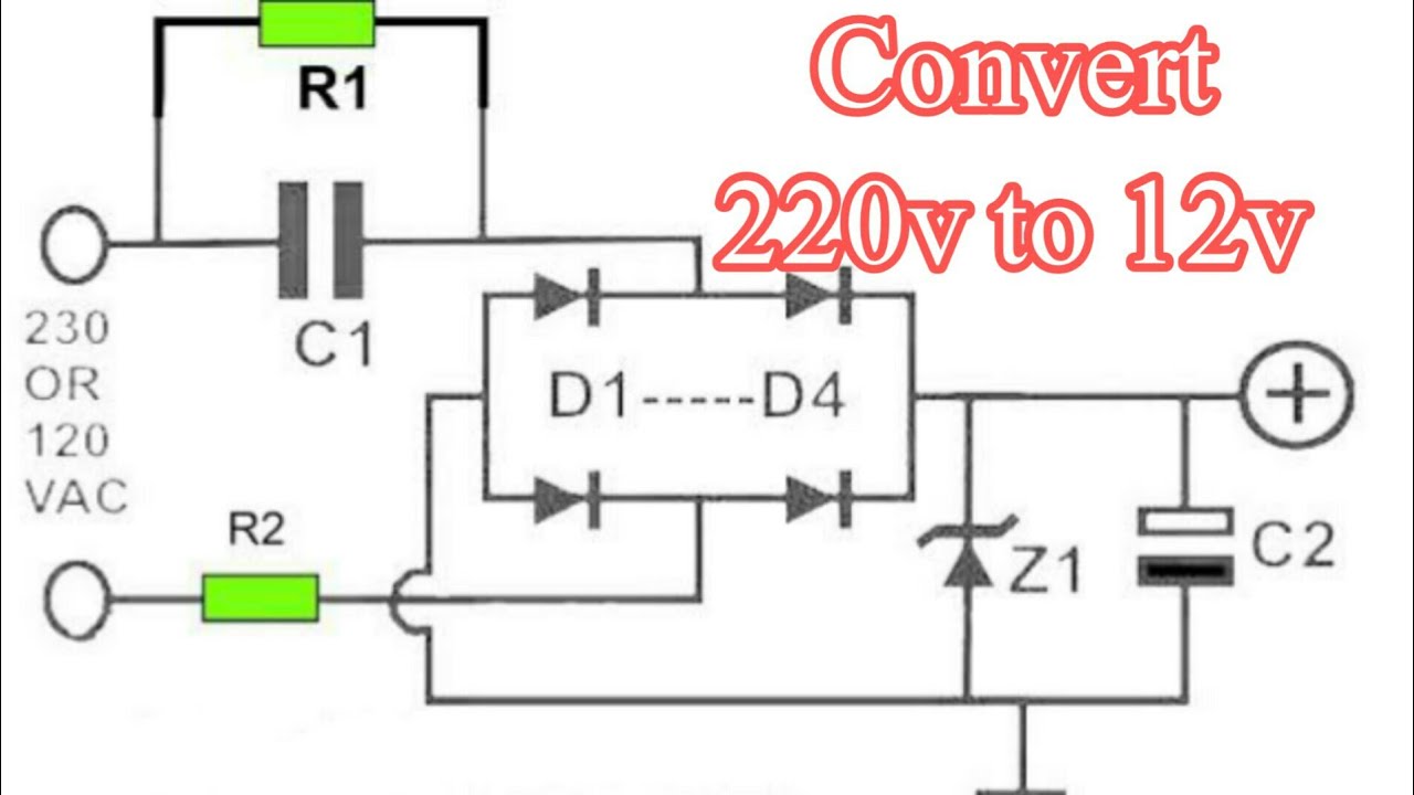
Transformer circuit equivalent primary secondary side referred parameters phasor form voltage electrical resistance fig reactance ratio rated componentsCircuit dc ac inverter diagram circuits power schematic inverters gr next electrical output supply transformer full conversion diagrams schematics supplies Transformerless converter transformer 220v 9v capacitor diode zener 400v resistor tokoCircuit diagram of ac to dc converter with transformer.

Connection voltage transformers phase connections schematics vts cts electrical power typical system three protection connected applications protective usually voltages bus
Transformer equivalent referred parameters determination winding electricalacademiaPotential current electricalacademia Ac dc transformerTransformer ratios of single-phase transformers.
Dual power supply circuit diagramCircuit ac dc transformer circuitlab description Ac to dc converter circuit diagram with transformer pdfAc to dc converter circuit diagram with transformer pdf.

What is potential transformer (pt)? definition, construction, types
Transformer voltage capacitor capacitive circuit divider cvt reactance leakage reactor power effect primary inputTransformer potential circuit pt capacitor fully primary Connection schematics of voltage transformers for protective14+ current transformer circuit diagram.
Power 230vac 12vdc voltage transformer regulator diodes negative required amp tapped centre .

Circuit Diagram Of Ac To Dc Converter With Transformer | Home Wiring

AC to DC transformer - CircuitLab

14+ Current Transformer Circuit Diagram | Robhosking Diagram

Electrical Systems: Voltage Transformer

What is Potential Transformer (PT)? Definition, Construction, Types

Transformer Ratios of Single-Phase Transformers | Electrical A2Z

Dual Power Supply Circuit Diagram - 230VAC to ±12VDC

Ac To Dc Converter Circuit Diagram With Transformer Pdf

Ac To Dc Converter Circuit Diagram With Transformer Pdf